| Manufacturer: | Scratch |
|
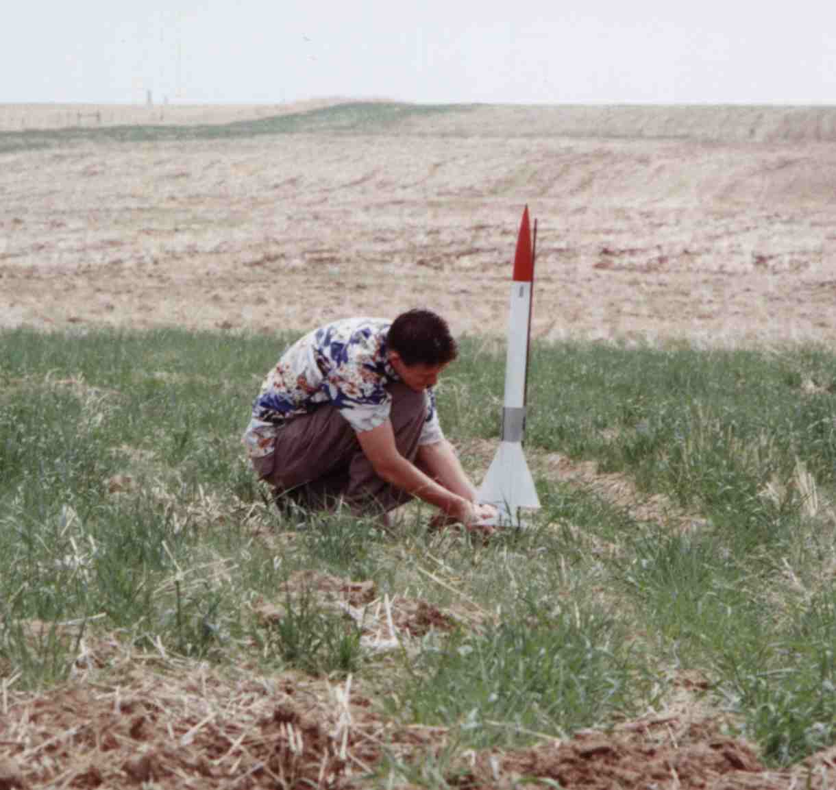
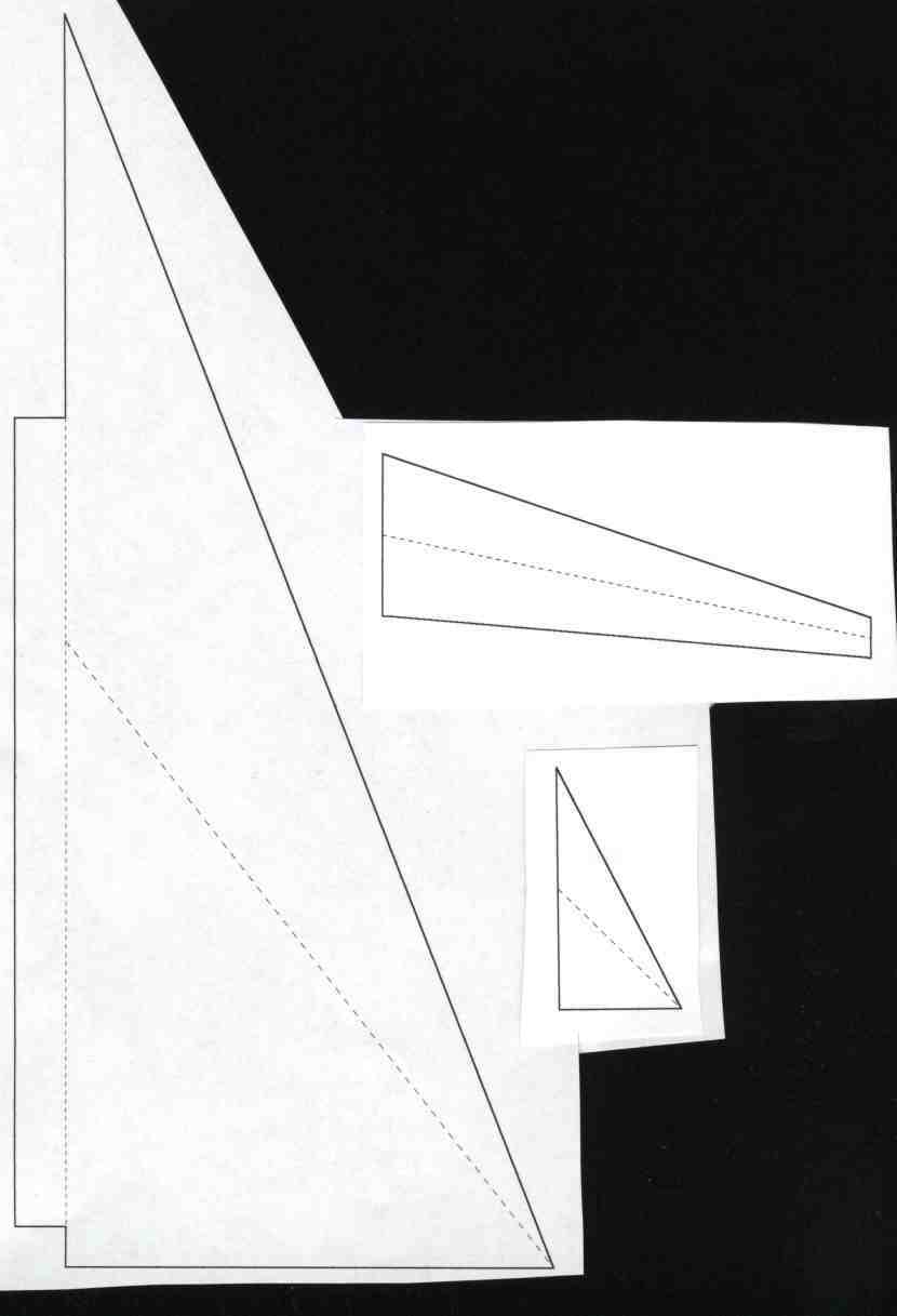
Mark 1X Hi, my name is Mark Shamburg-Donohue. I'm a 17 year old high school junior. I live in Denver, Co.Ýand I've been flying model rockets since I was 12. I just got into high power rocketry this winter when I fired an Aerotech 1357T reload for a physics class project My favorite subject is chemistry and I have done a lot of work in the chemistry area of rocketry. I am currently designing a hybrid motor, that I would like to build this summer. The motor employs certain unique design features, which I think will make it a very interesting project. I plan to patent the design if all goes well. A science teacher/ friend/ head of IAAS (science club)/ all around great guy, named Jim Moravec is helping me find an internship in one of the many aerospace companies in Colorado. I will be starting college in the fall of 2001, and would like to major in chemistry, with minors in either mechanical engineering/drafting or physics. Once I graduate I would like to work for either the military or the aerospace industry developing propulsion systems. I would also like to get a master degree in chemistry. This is my first high power rocket. Ever since I downloaded VCP about six months ago, I've designed over 50 rockets. This rocket was initially named the "She's a Goer" after the B-29 my grandfather flew over Korea, and was designed to slightly resemble the beautiful bird. The rocket originally had a 1.5" long elliptical nose cone, but do to unavailability of this (more aerodynamically sound) design I had to settle on a 9.5" long tangent ogive. Since the design no longer resembles the She's a Goer, I had to come up with a new name for it. Since the rocket nowÝresembles a missile I decided to give it a military sounding name. I settled on "Mark 1X". The "1X" comes from this being the first design of my own that I've built and the fact that its an experimental design. Unlike some entries that are just modifications on pre-existing rockets this is an entirely original design. This baby has 12 fins! Some people might think that having 12 fins makes the rocket overly difficult to build but the advantages outweigh the difficulty of building it, which by the way was no more difficult than any other rocket (only slightly more time consuming). Most of the surface area comes from the main fins, which are located 2.5" from the bottom and have a surfaceÝarea of 11.625 sq." each. The aforementioned advantages come from the canards which are small fins at the front of the rocket which don't have a large enough surface area to create any stress problems but function to split the air stream and lower the amount of turbulence created by the main fins. The rear fins are mostly cosmetic, but also add to lower the amount of turbulence whenÝ the air stream closes around the end of the rocket. |
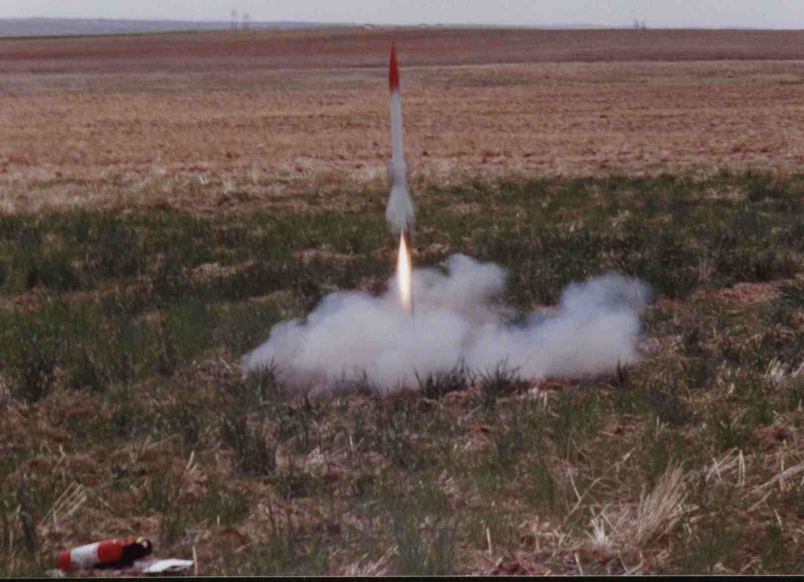 Here's the Mark 1X on the F25-6. This picture was taken by my dad. The gray thing you see above the main fins is the fly away launch lug.
|
|
Most of the major components are easily acquired from Public Missiles Ltd. All exceptions are marked with an *
Nose Cone - Public Missiles Ltd. Part Number PML PNC-2.1. The nose cone is a 9.5" long, tangent ogive. The original design used a 1.5" long elliptical nose cone. I had to make the nose cone out of balsa wood, because no companies that I have found carry that shape. I also made a fiberglass version of the nose cone by making a Plaster of Paris mold of the balsa nose cone and laying in glass. Body Tube - Public Missiles Ltd. Part Number PML QT-2.1. This rocket uses the Public Missiles "Quantum Tube" which is a plastic of some sort that makes the rocket a lot easier to finish. The body tube is 30" long, with 5" long fin slots starting 2.75" from the bottom. Public Missiles will cut and slot the tubes for you at their shop. I highly recommend this service. There are four 3/32" fin slots. Fins* For my fins I used 3/32" acrylic sheet, but you can also use lexan (polycarbonate), or birch plywood. Rough cut the fins about 1/8"outside the line, then glue them together and sand them down to size. After they have been sanded to the proper size remove the plastic film. This Rocket has 12 fins. From now on I will refer to the main fins as the fins, the front fins as the canards, and the rear fins as the rudders. Motor Mount - Public Missiles Ltd. Part Number PML MMT-1.5 x18. The motor mount is 18" long, and unless you plan on flying this rocket a "J" motor, (in which case you might have a little trouble packing the parachute) cut the tube to 12" in length. Centering Rings - Public Missiles Ltd. Part Number PML CR-2.1-1.5. I used two, but if you want to cut a groove in the fin tabs you can use three. Motor Adapter - Public Missiles Ltd. Part Number PML ADPTR-38/29. I plan to use this rocket as my Level One Certification when I turn 18. But until I am certified I will fly this on 29mm motors so I added a 29mm friction fit adapter. Motor Retention Instead of using several layers of tape, I decided to employ the use of a motor retention system. But because of the limited space between the motor mount and the body tube, I had to design a motor retention system myself. Kaplow Klips just wont fit. The assembly of the retention system is detailed below. System* Parachute* Public Missiles Ltd. sells a 48" rip stop nylon parachute, but I was unwilling to shell out another 25 bucks for it. So I made my own! I bought 2 square yards of camouflage rip stop cotton which I used in lieu of nylon. For suspension lines I found a pack of parachute cord which is 40' of 1/16" braided nylon originally used for Army man-rated parachutes. Ejection Gas Baffle* Rather than shelling out another 15 bucks to buy a baffle I designed and built one my self, it also functions as the parachute mount. Its construction is detailed below. Shock Cord*
Step 1: Draw lines on the tube from the slots to the front end of the tube, and to the rear end. Then prepare the motor mount first by gluing the front centering ring 1/8" from the one of the ends of the tube with CA. After the CA dries epoxy the ring in place. Step 2: Prepare the second centering ring by adding the motor retention system, (see below). Step 3: Insert the motor mount into the body tube and position it so the motor mount tube protrudes 1/16" from the end of the body tube. Dry fit the rear-centering ring on the tube and mark the motor mount for epoxy/ fin fillets by inserting a pencil in the slots and running it back and forth. Step 4: Cover the pencil lines with epoxy and epoxy the rear centering ring º" from the end of the tube. Then insert the motor mount 'til the tube protruded 1/16" from the end of the body tube. Step 5: Place the fins in their slots, and pressed them down until the root edges contact the body tube. Step 6: After the epoxy gels, mask off the body tube except for a º" on each side of the fins. Then add the epoxy fillets to the fins. Step 7: Mask the tube for the fillets around the canards and rudders, then position and tack down the canards with CA. Add epoxy fillets to the canards after the CA dries. (Baking Soda makes CA dry!!!, saved me nearly an hour.) Step 8: After the epoxy from the canards gels, position and tack down the rudders with CA. After the CA dries add epoxy fillets to the rudders. Step 9: Filled the gap between the motor mount and the motor mount and the body tube (think rear centering ring) with epoxy and let the rocket sit for 24 hours for all of the epoxy to cure. Step 10: Attach the shock cord to the baffle then insert it into the tube and epoxy it in place. Using a 10" piece of 3/8" flat elastic tether the nose cone to the parachute. Step 11: I worked out a paint scheme and primed the rocket. After the primer dried, I masked the rocket and painted it. Step 12: Sleep. Wake up in the morning and admire a work of art.
Motor Retention System and Assembly In this rocket there is about 6mm of space on each side between the motor mount tube and the body tube. No where near enough room for tee- nuts. So I had to come up with my own design. Materials Notes 1/8" brass threaded rod - 3/16" brass washers - You'll need 4 washers for two posts, if you want a 4-post retainer you'll need 8. 1/8" brass nuts - You'll need 4 nuts, if you want a 4-post retainer you'll need 8. º" wide brass strap - You'll need 2 each 1.5" long straps for a 2-post retainer, 4 for a 4 post version. Step 1: The threaded brass rod that I bought came in a 12" piece. I cut two 2" pieces and sanded one end of each to a taper. Step 2: I mixed a small batch of epoxy and when it started to gel, I dipped the rough end 1/8" into the epoxy to make a larger diameter shoulder. Step 3: I drill two 9/64" holes 180 degrees apart and sanded the edges of the holes. I'm only using two retaining posts, put you can use 3 or 4. For 3 space the holes 120 degrees apart. For 4 space the holes 90 degrees apart. Step 4: I put the two threaded rods through the holes and covered the area I didn't want epoxy to get on with masking tape. After making sure the rods lined up 90 degrees with the centering ring I epoxied them in place. If you are using a relatively thin epoxy it is a good idea to let it almost gel before using it. It will be much thicker. Step 5: Drill a 9/64" hole º" from the end of the pieces of strap, and de-burr the hole. Step 6: Put your motor into the tube and mark off the distance of the strap to the lip of the motor. (Or the point you want to apply pressure to with the straps.) Step 7: At the mark bend the strap so it forms a rounded of 90 degrees angle. (In the shape of an L) Now round over the strap where it will contact the motor. To use it first put the motor in the mount tube. Then thread one nut down just below the level of the motor and put on one washer. Slide the strap down, and then the last washer and nut go on. Excluding drying/curing time it takes less than 10 minutes to make.
Half the fun of building rockets is designing and building all of the parts of the rocket. This Ejection baffle unit cost me less than $5.00 to make. Materials Notes Bulkhead Bulkhead plate with eyebolt Centering ring 1-2 square feet of screen Step 1: Drill a circle of holes around the center hole in the bulkhead plate and sand the edges of the holes. About 1/8"- 1/4" should be right. Step 2: If necessary widen the hole in the middle and screw the eyebolt all the way down. Epoxy the eyebolt in place on both sides of the plate and make sure to get a good bit of epoxy in the open loop of the eyebolt. Step 3: Cut the bulkhead tube about 3 *" long. Insert the bulkhead plate in about *" and epoxy it in place on both sides. Step 4: cut a circle of screen slightly larger in diameter than the hole in the centering ring. Put a ring of epoxy around the hole in the centering ring. When the epoxy is just starting to gel press the screen down in to it. Waiting will save you a lot of effort. Step 5: Look at the rocket and admire what you've done so far. Step 6: After the epoxy has gelled enough to make it hard to the touch, wad up the rest of the screen and push it into the bulkhead. Do not stuff the bulkhead to full. Step 7: Epoxy the centering ring onto the bulkhead plate. The outer diameter of the ring should match the outer diameter of the tube. Step 8: After all of the epoxy has cured, tie your shock cord to the eyebolt. With a stick put a layer of epoxy inside the body tube about *" from where the baffle will rest. Insert the baffle into the tube and press it down until it contacts the motor mount tube.
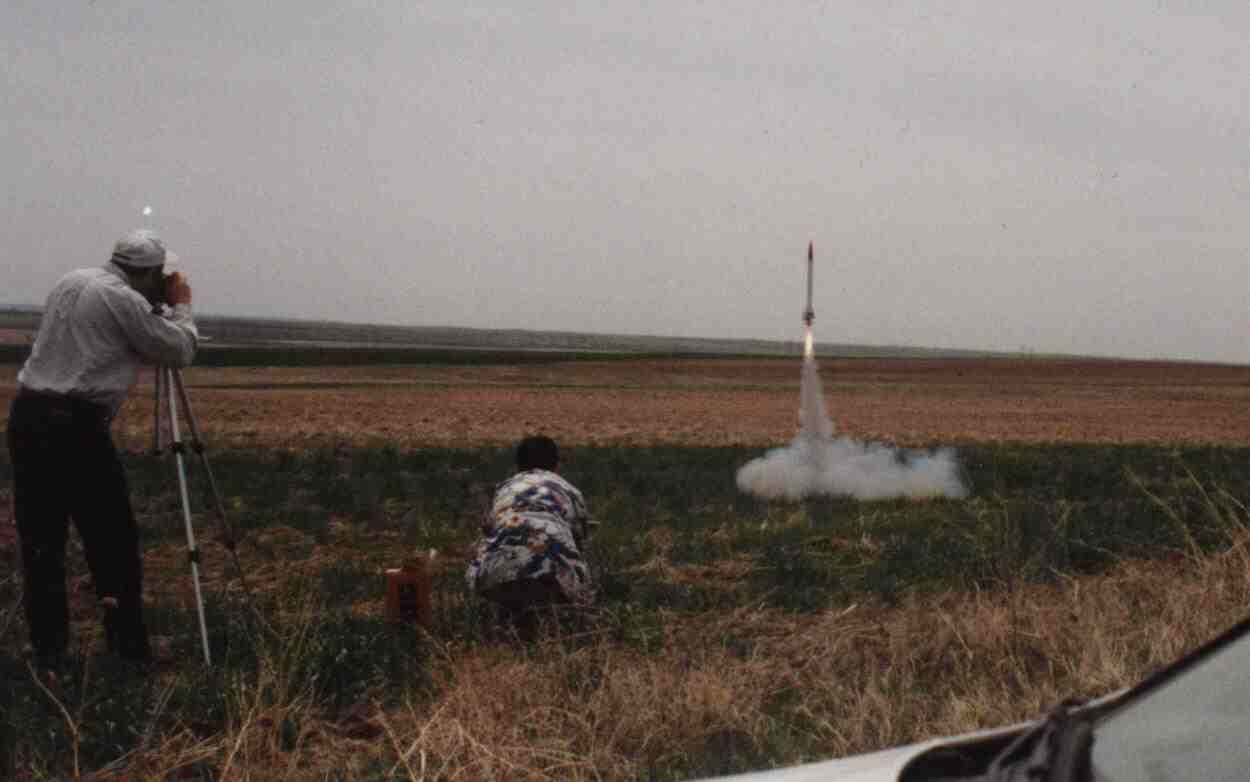
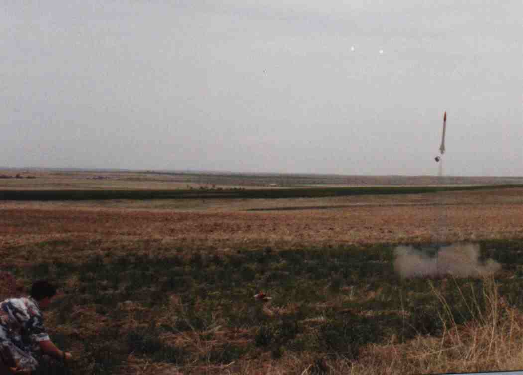
After finally getting everything ready to go with the rocket I realized I had forgotten to build the launch tower that I was going to use rather than using launch lugs. So I cut a piece of sheet tin to about 4" wide and about 2" longer than the circumference of the tube and made a "fly away launchÝlug" like the one on Bob Fortunes page. After picking up a friend, and stopping to get some fast film, we drove straight east of Denver for about an hour and a half until we found a nice open spaceÝwith no fences. We walked out into the the field and set up pad. I loaded the first motor into the rocket. It was an Aerotech F25-6 white lightening. While rocksim predicted the rocket would fly to about 1102', the rocket had a very curved flight, and flew in a large arc, and only achieved an altitude of about 800'. The rocket was recovered about 100 yards fromt the pad. The fly away launch lug worked perfectly and released from the rocket about 2-4 feet off the rod. The second flight took off on an Aerotech G80-10 blue thunder, and lifted off extremely fast and extreemly straight. After burn out the rocket started to coast a little off coarse. The ejection charge fired perfectly at apoge, which although Rocksim only predicted an altitude of 1970 feet was about 2200 feet, the parachute was ejected way too violently and zippered the tube about 12 inches. The over-powered ejectioncharge also blew out the motor retainer and adapter, and pushed the entire (epoxied in) motor tube and baffle units about 8" up into the tube. The parachute lines tangled in the torn tube and the rocket free fell from about 2200 feet. When recovered, the rocket was in severe condition. It lost all of its fins except the main fins, which wereÝfiberglassed to the tube. The fall had even broken the fiberglass seem. Well, one more rocket to add to the collection. |
      |
 |
 |
